Aerospace / Research
Project Saturn
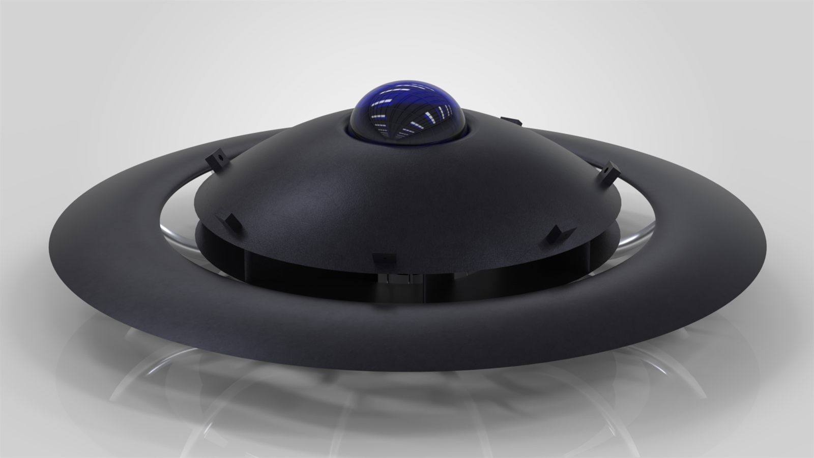
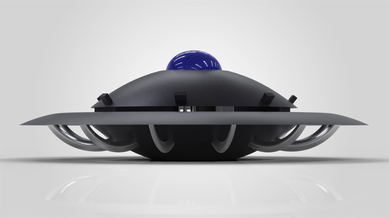
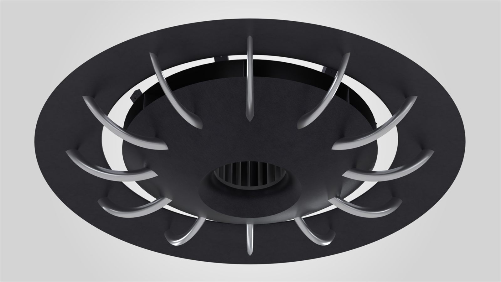
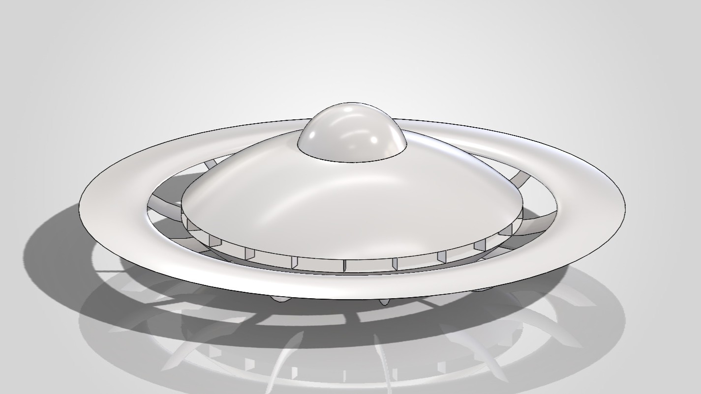
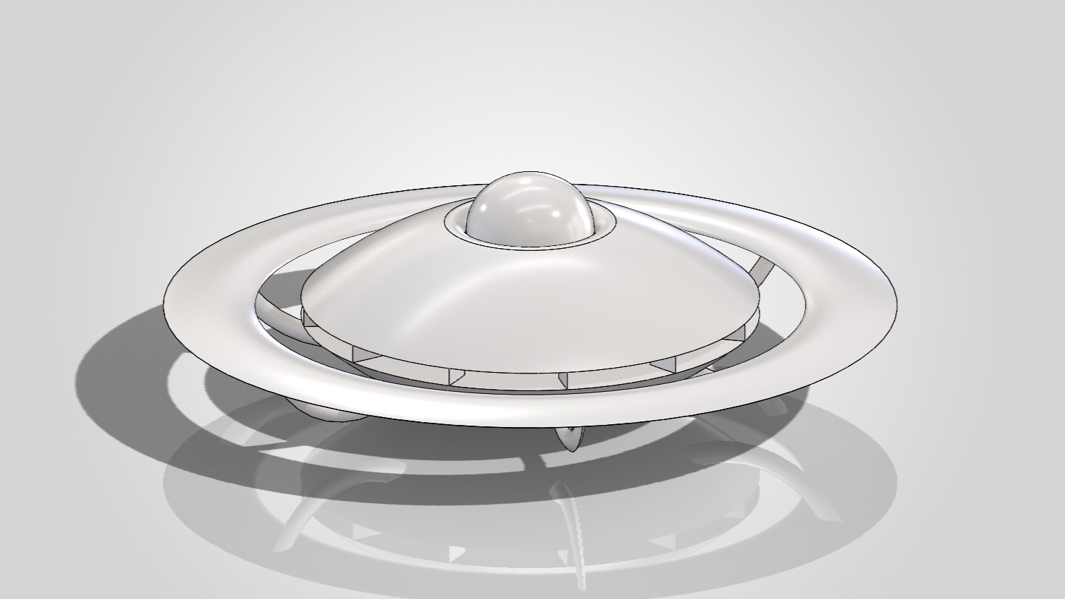
Project Saturn is a circular-wing VTOL that makes its own lift by blowing air across itself instead of moving through it. A central fan draws air from the bottom, through the body and throws it outward over a ring-shaped wing, and the saucer form falls straight out of that physics. It is an MSc thesis and a direct continuation of Hovering Through New Horizons.
Reverse the wing
An ordinary wing only works once the whole aircraft is moving fast enough. Project Saturn breaks that link: the wing stays still and a fan supplies the airflow, so lift no longer waits on forward speed. Feeding that flow evenly is what forces the wing into a full ring driven from the centre, and the round body follows from there.
The Air Force tried this
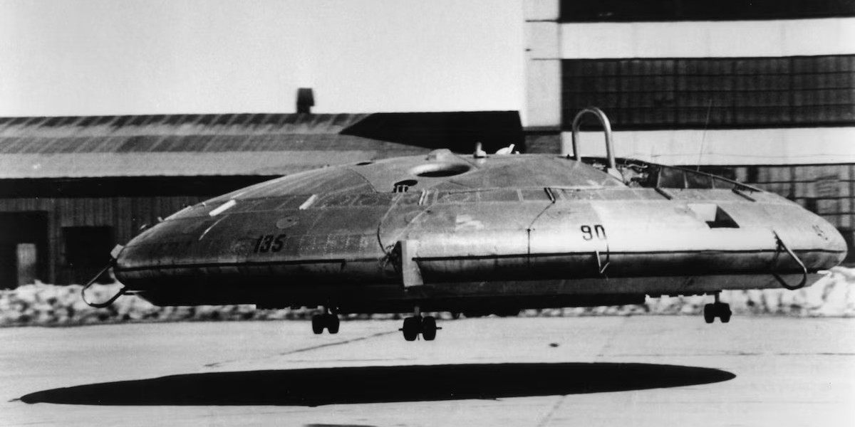
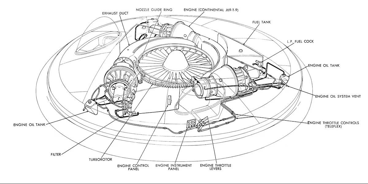
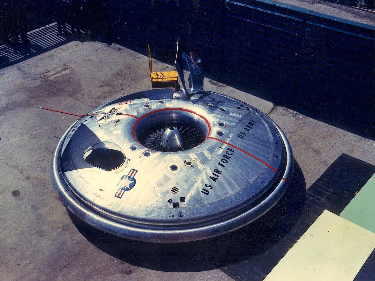
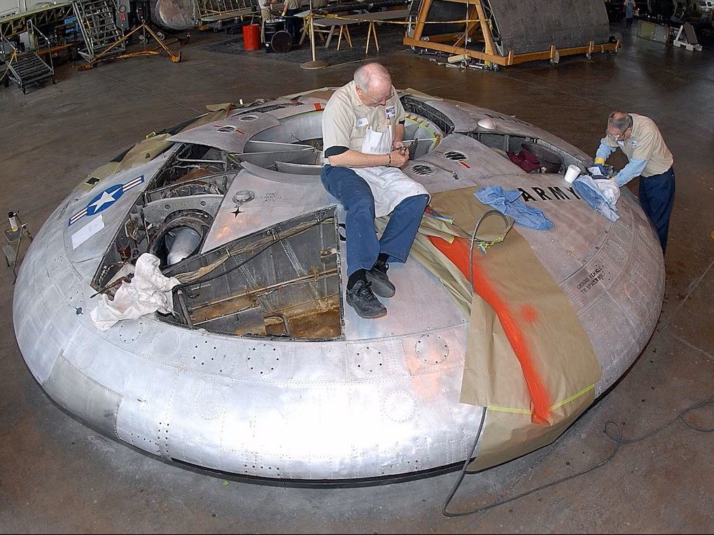
The disc was the result, not the target, and the resemblance to an old idea only became clear afterwards. In the 1950s the US military chased the same shape twice: Project 1794, a classified saucer meant to reach supersonic speed on the Coanda effect, and the VZ-9 Avrocar (link), which actually left the ground. Both fought the same instability and neither was tamed. Arriving at their shape from clean physics, decades later, reads as validation rather than influence.
How it works
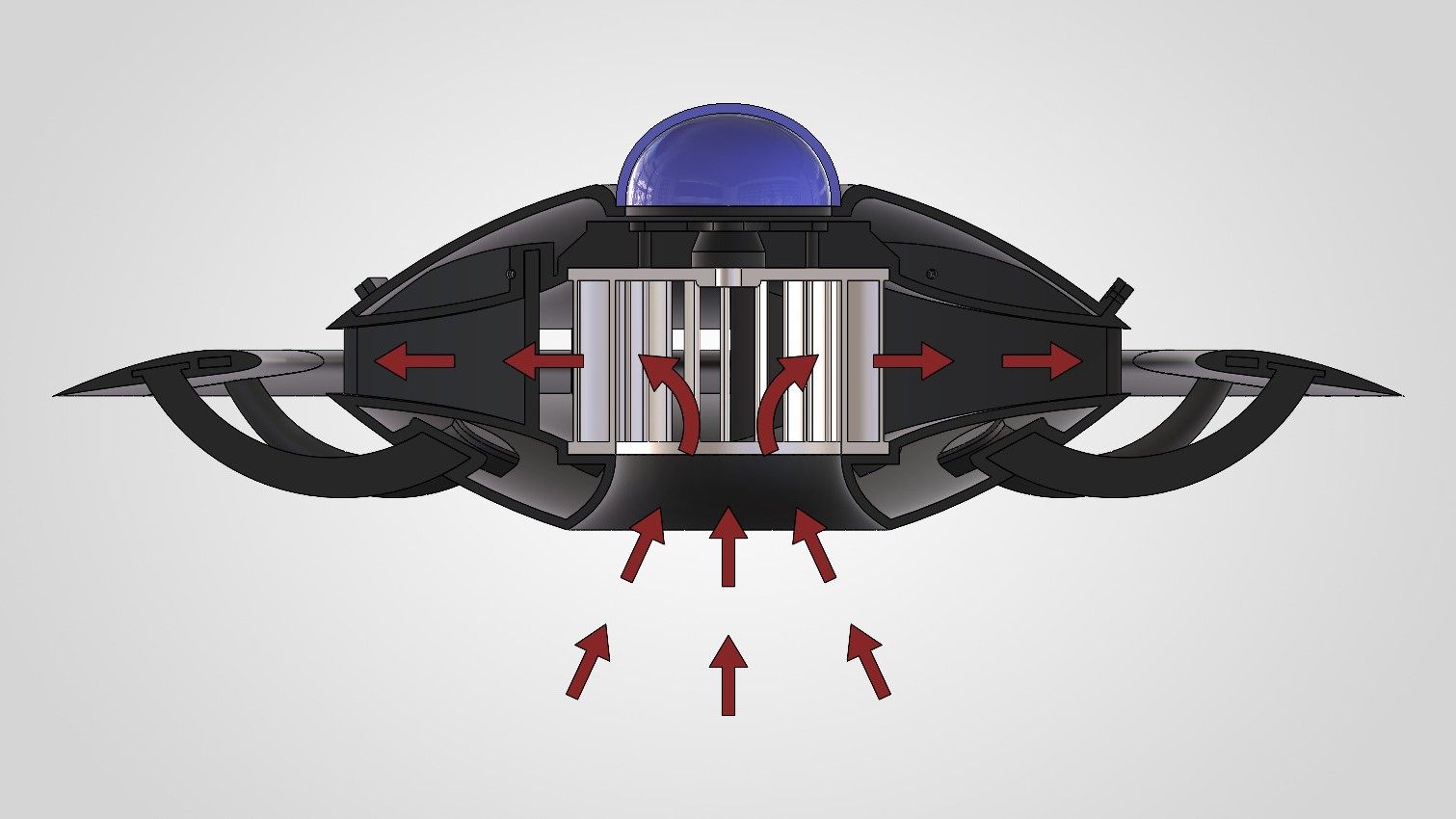
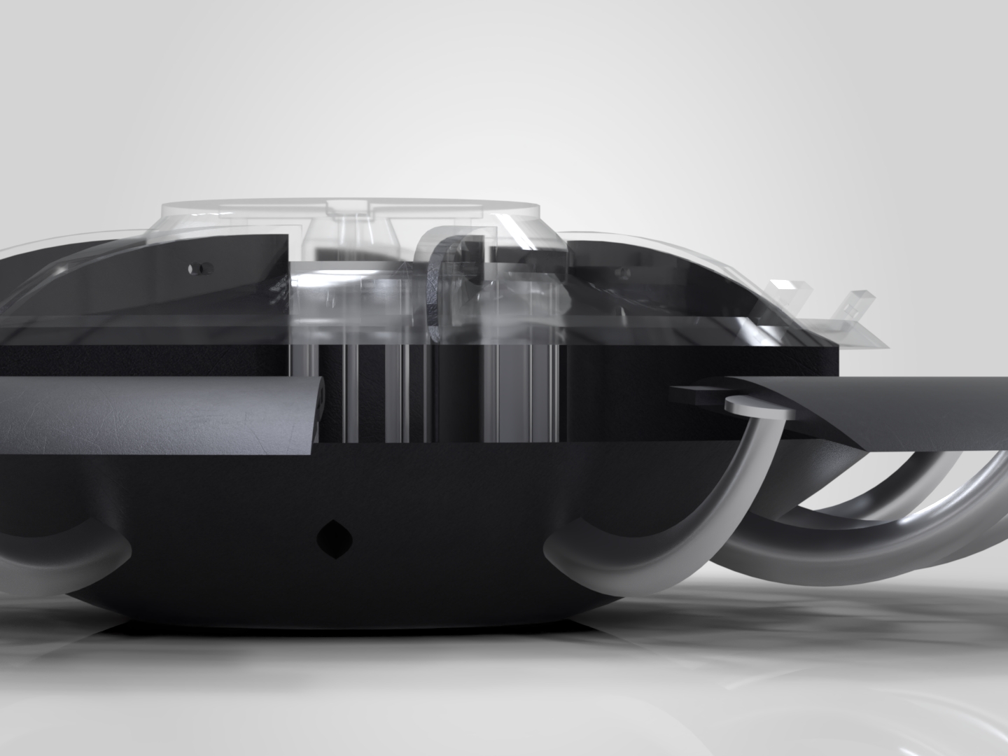
- Draw. A centrifugal fan pulls air up into the centre of the body from below.
- Spread. A radial duct turns the flow outward and feeds it evenly around the rim.
- Accelerate. The air speeds up as it passes over the curved circular wing.
- Lift. Faster air above the wing drops the pressure there, and that pressure difference is the lift.
- Straighten. A ring of stators takes the spin out of the flow before it leaves.
Designing the wing
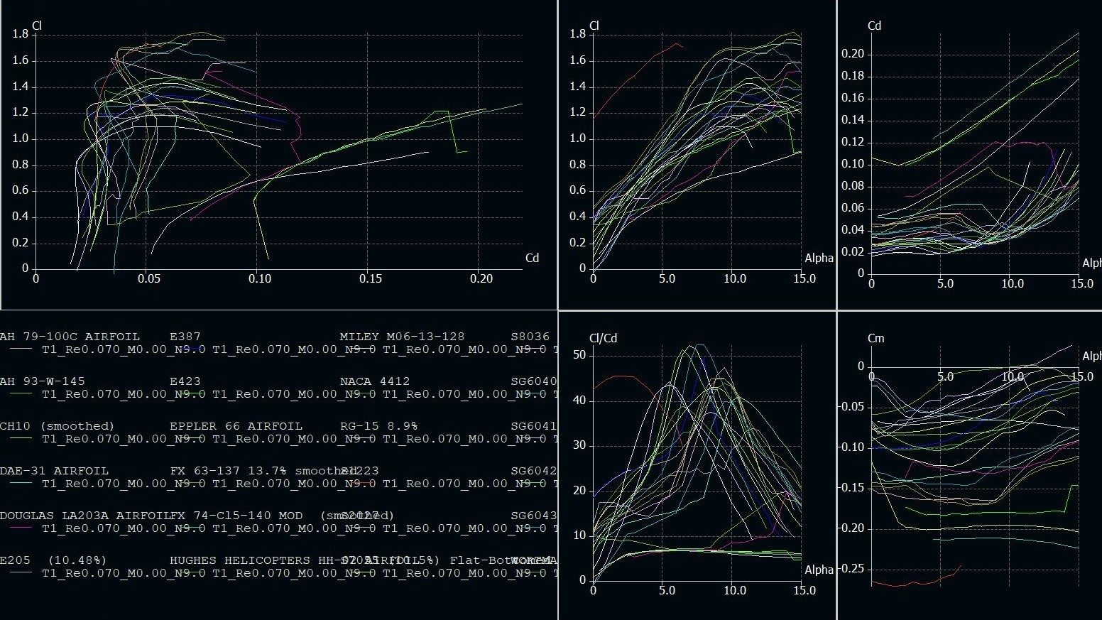
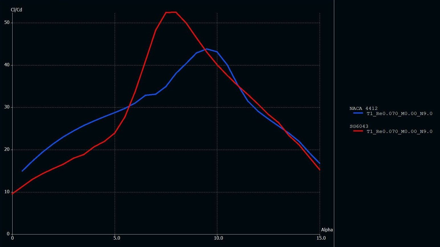
The wing section was chosen, not assumed. Twenty-five airfoils were screened at a Reynolds number of 70,000, the regime this scale model operates in, and ranked on lift-to-drag ratio. The SG6043 came out ahead of the common NACA 4412, and it set the profile carried through the rest of the design.
Proving it in CFD
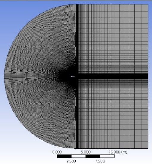
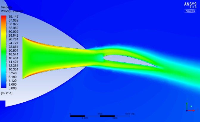
Confidence was built one step at a time. The simulation worked up through six stages, from a 2D airfoil to the full ducted circular wing, each one checked for grid independence before moving on. The velocity contours below show the flow accelerating over the wing, which is where the lift comes from.
Driving the air
At the centre is a centrifugal fan, the part that does the real work. It pulls air up from below and throws it outward off curved blades, so the flow leaves faster and wider than it arrived. The blades are forward-curved, the shape best suited to a small fan moving a lot of air, and they were sized to fit the craft: set the body first, then shape the blades to feed it.
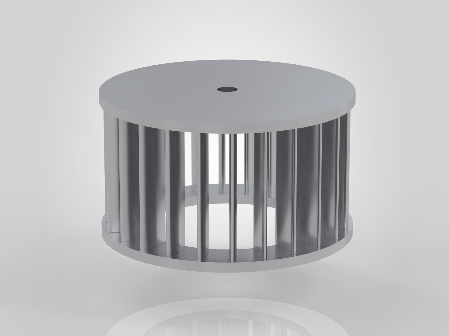
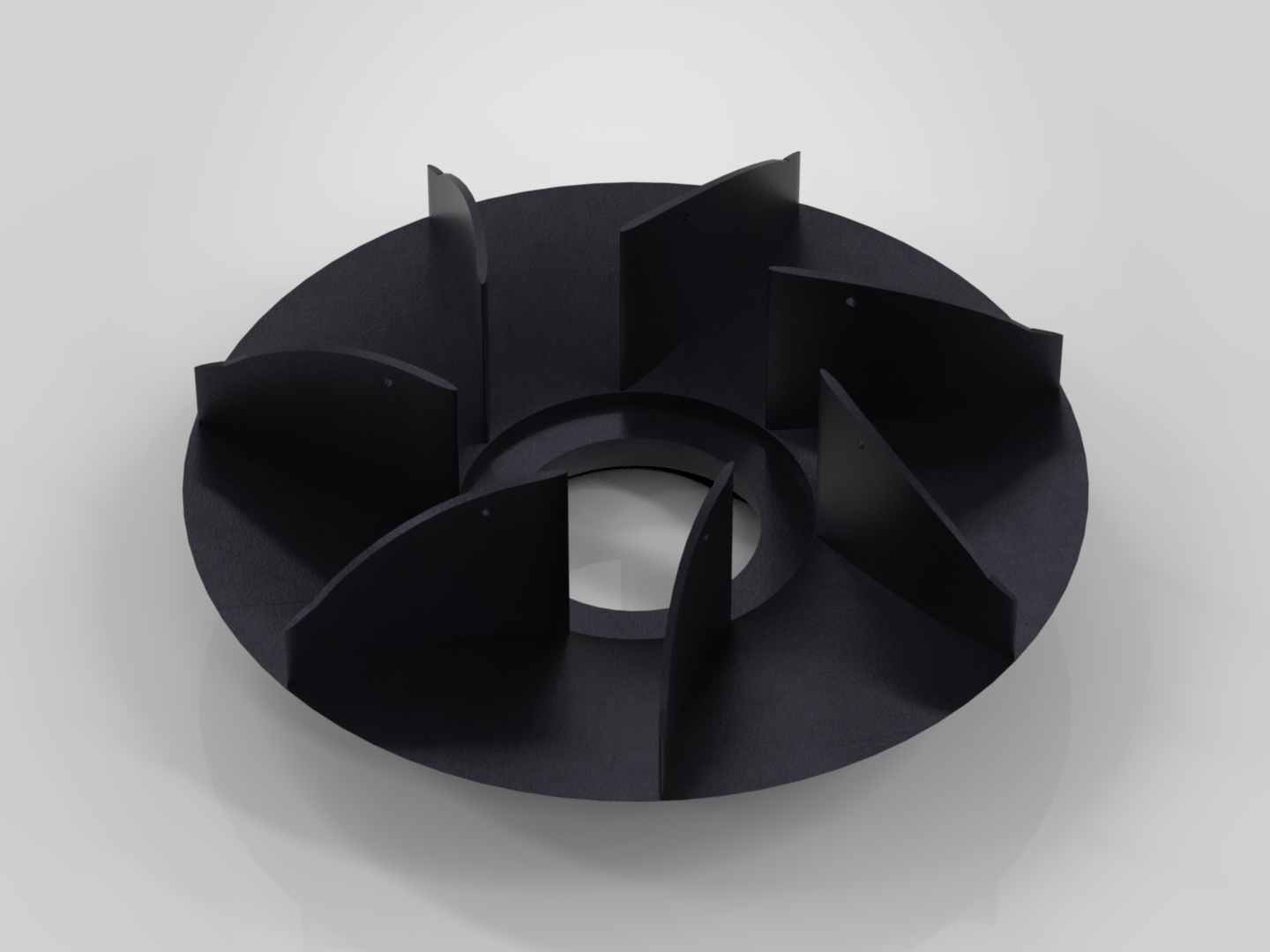
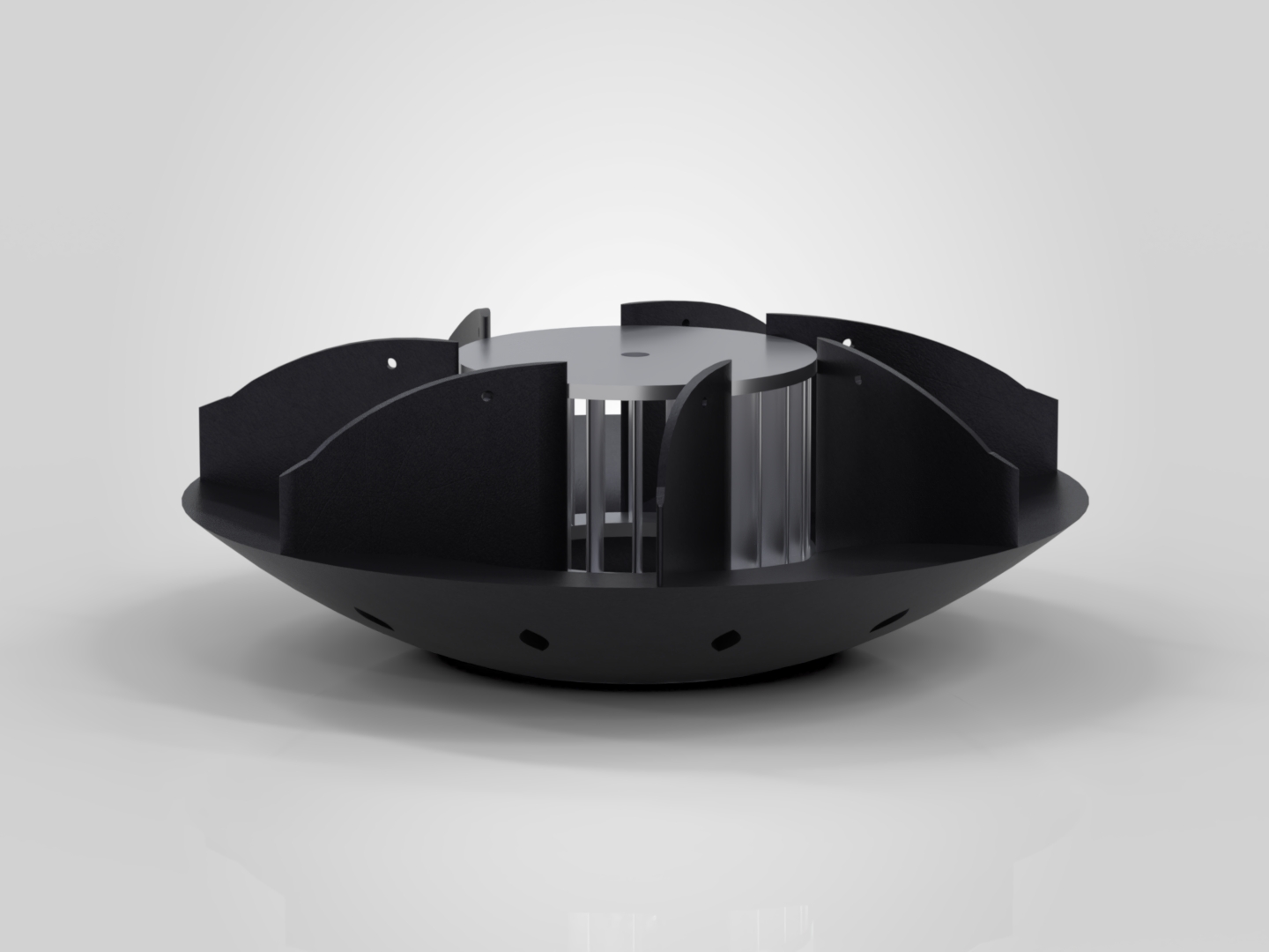
The fan leaves one problem behind. The air comes off it spinning, and that spin is wasted energy that adds nothing to lift. A ring of stators corrects this, meeting the flow at the angle it leaves the fan and curving it back to straight, gently enough that it never separates from the surface. The vane count is a deliberate choice: 7 vanes against the fan's 24 blades, set so the two never align into a resonance that could shake the craft apart. Those same vanes also act as structure, tying the top and bottom halves of the body together.
Building and testing it
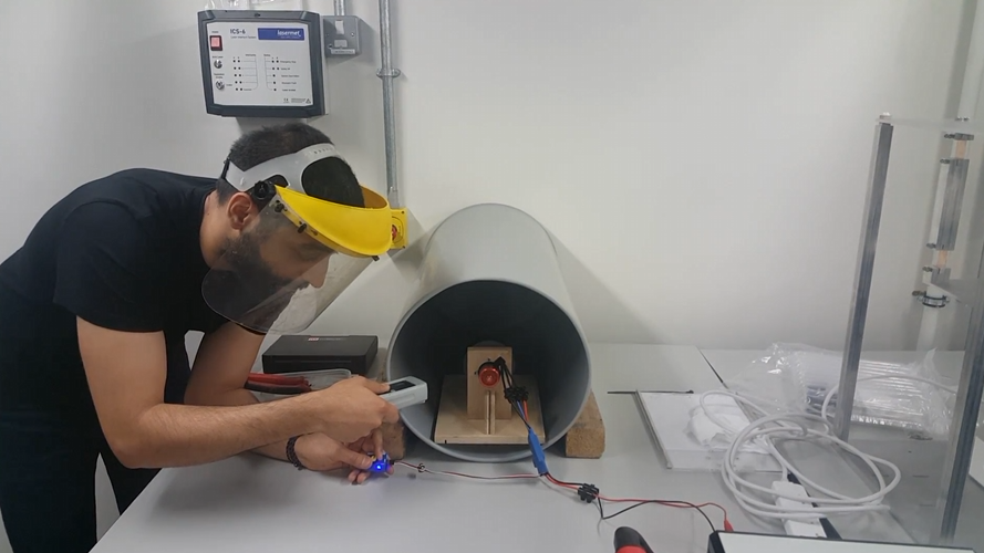
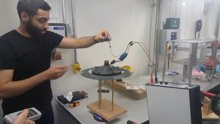
The design left the screen as a physical scale model. It sits on a wooden stand over a scale, so the lift it makes shows up as a drop in measured weight, with an anemometer reading the air it moves and a brushless motor spinning the fan. Lift and mass flow were recorded against fan speed, up to 5,800 rpm.
The honest result
The numbers are reported as they came. Theory predicted 14.12 N of lift, CFD predicted 3.36 N, and the physical model delivered 0.31 N, measured at 5,800 rpm, past its design speed. The concept lifts, but it is still far from efficient. Stating that gap plainly is the point, and it marks where the next version starts: variable wing angle, control surfaces, and a tighter duct and stator design.
Previous prototypes
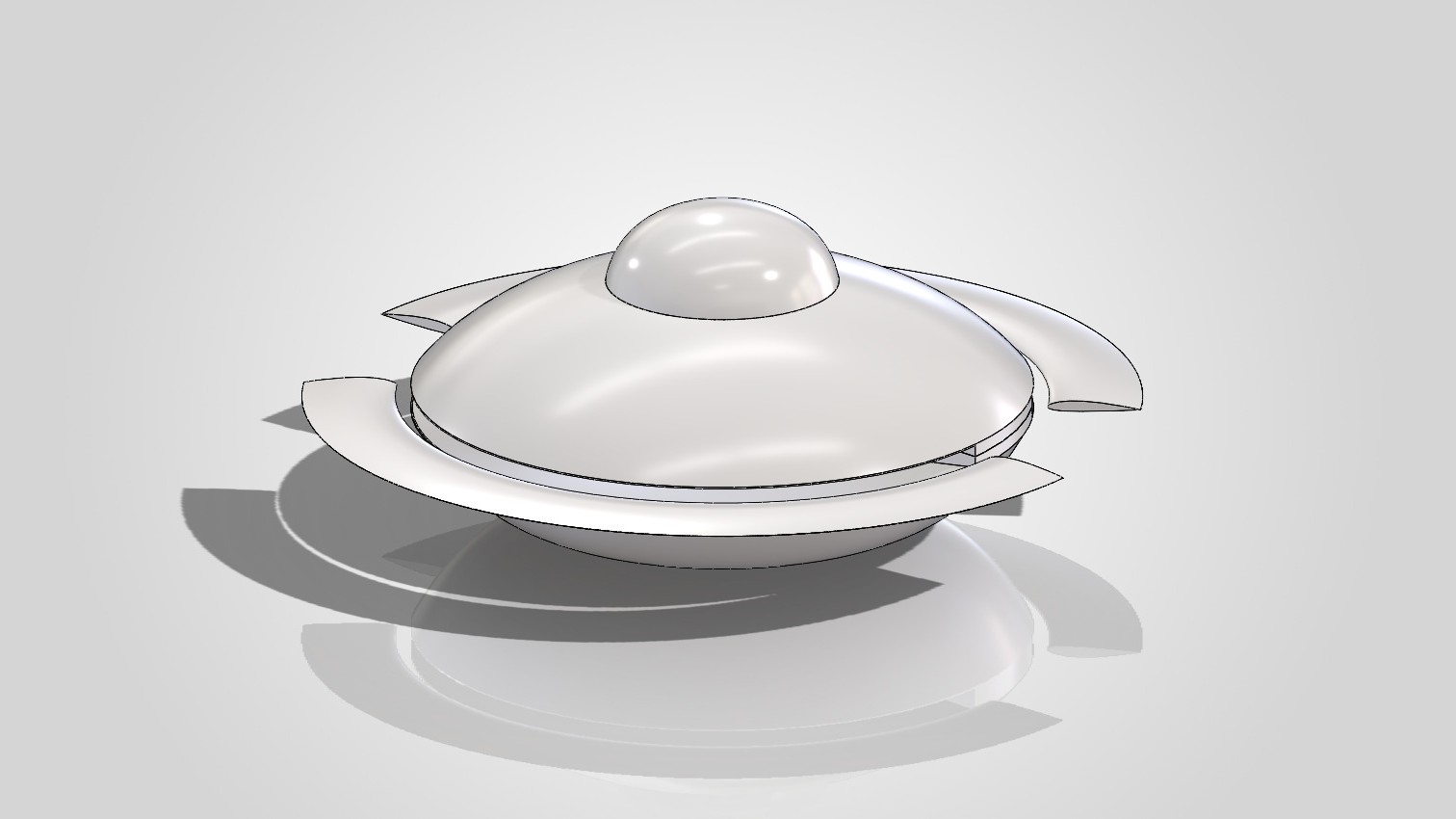
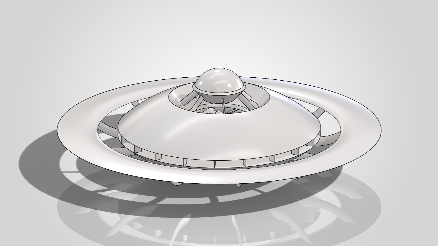
The final model was the last in a line of earlier builds. These are the prototypes that worked out the shape and the internals along the way.
The full thesis carries the sizing, the six-stage CFD validation, and the experiment in detail.