Mechanical / CFD
Droplet
Droplet is an atmospheric water generator: it condenses the humidity in indoor air into clean drinking water. The prototype ran, but reached only a fraction of its target. Airflow through the device was heavily restricted, and heat was leaking out of the thermal path along the way. Leading the project and owning the mechanical design end to end, from the airflow analysis through the CAD to the parts tested on the bench, is the work shown here: the diagnosis behind that shortfall and the redesign of the parts that move the air and manage the heat.
The starting point
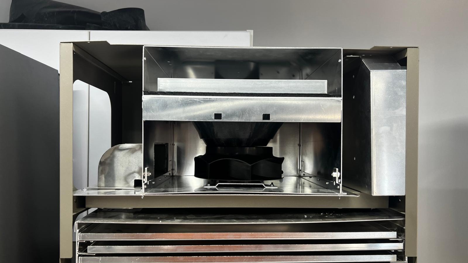
Droplet arrived as a clean-looking prototype that fell well short of what the client needed. It produced roughly 4 litres a day against a target of 15 to 20. The job was to find out why and close the gap.
The investigation traced three issues stacked on top of each other. The airflow analysis behind the design didn't reflect how the air actually moved, the build concept followed from it, and the fan at the centre was a weak foundation that the whole device had been built around. Each one alone held the machine back. Together they starved it.
That set the work: rebuild the analysis from first principles, then fix the hardware the numbers pointed to.
A clean-sheet redesign would have been the stronger answer, but the three-month clock ruled it out. The work targeted the changes that returned the most performance for the time available.
Reading the airflow
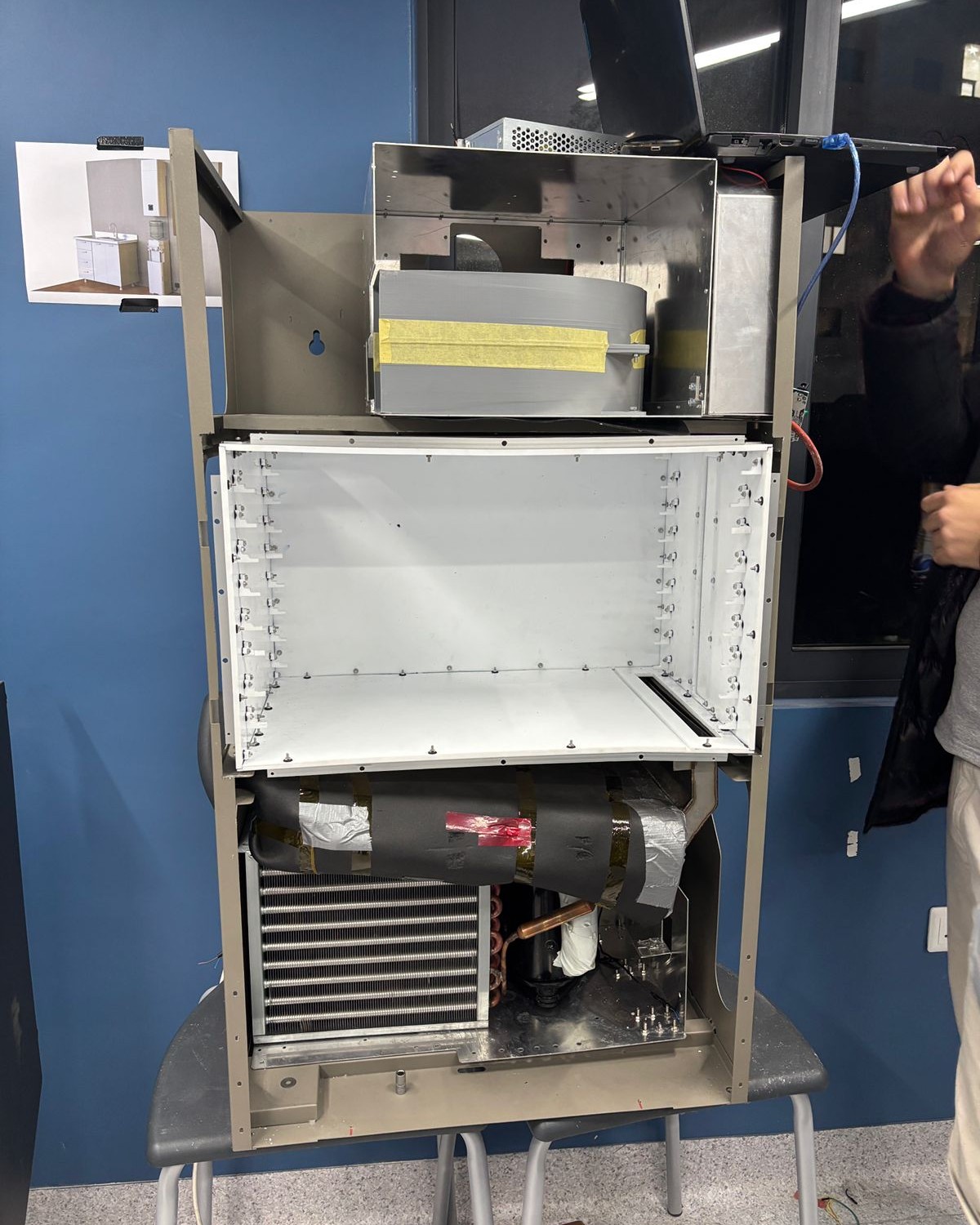
Air has to travel from the fan, through a stack of sorbent trays, and back out. Modelling that path properly showed where it was being throttled, and the answer was not the fan's power. It was everything around it.
- Pressure-loss model. Built from first principles. 91% of the pressure loss sat in the bends, not the trays.
- Fan running blind. No scroll housing, so most of its output spilled into open space.
- Heat and mass balance. Desorption dominated the cycle, driving the high power draw.
- Validated. The rebuilt numbers matched the measured shortfall and set the brief for the fixes.
The fixes
Each change answered a number from the analysis. Nothing was added for its own sake.
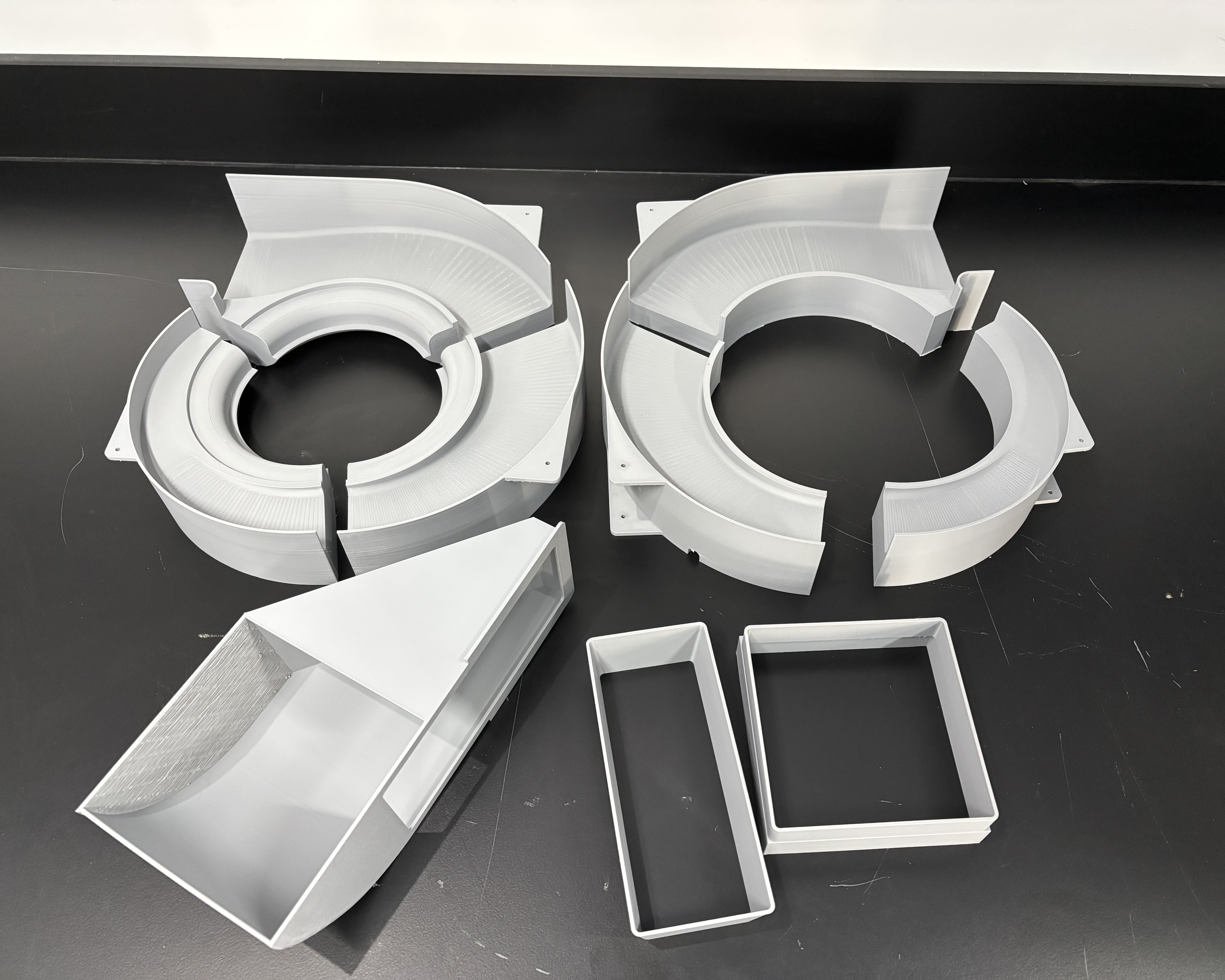
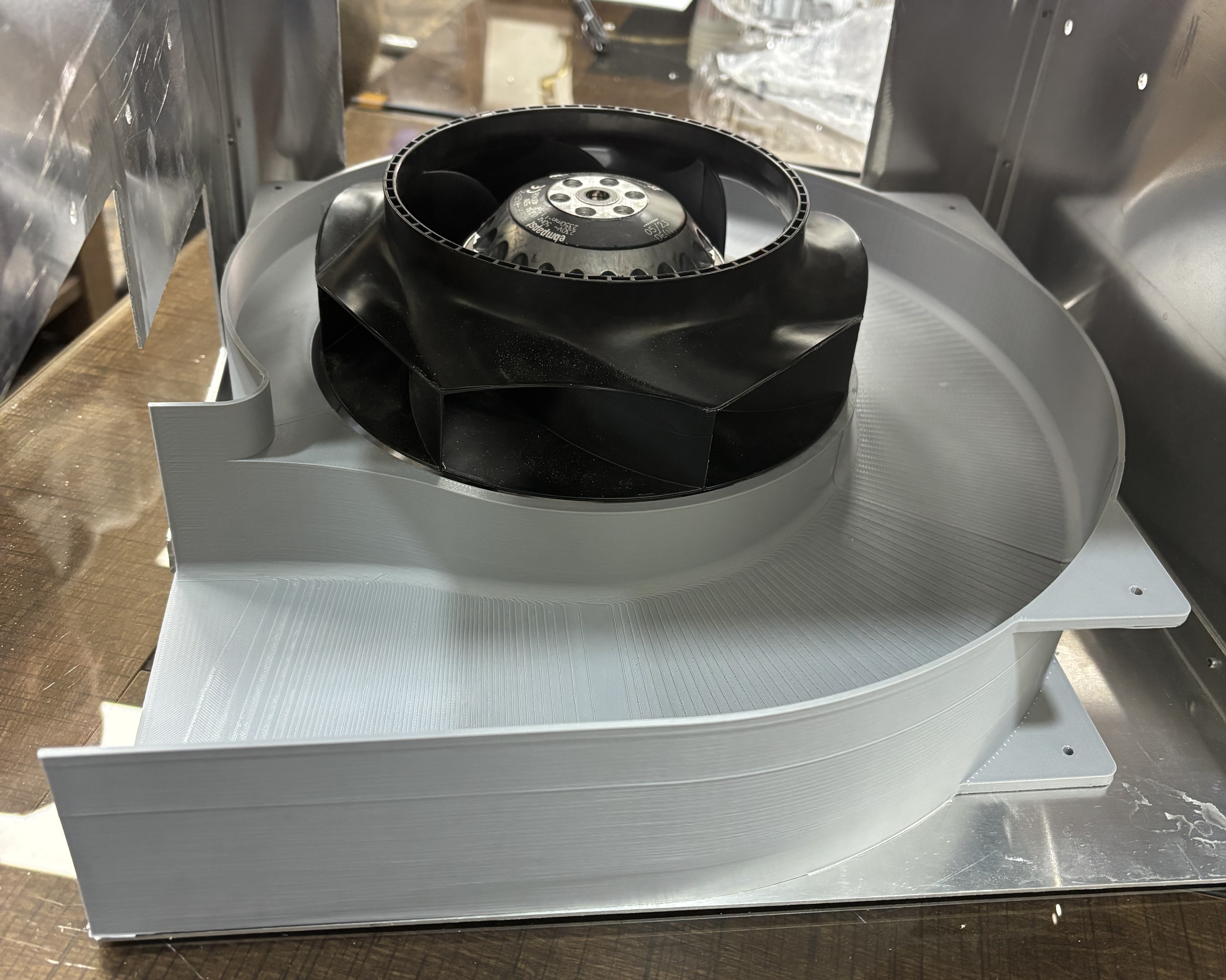
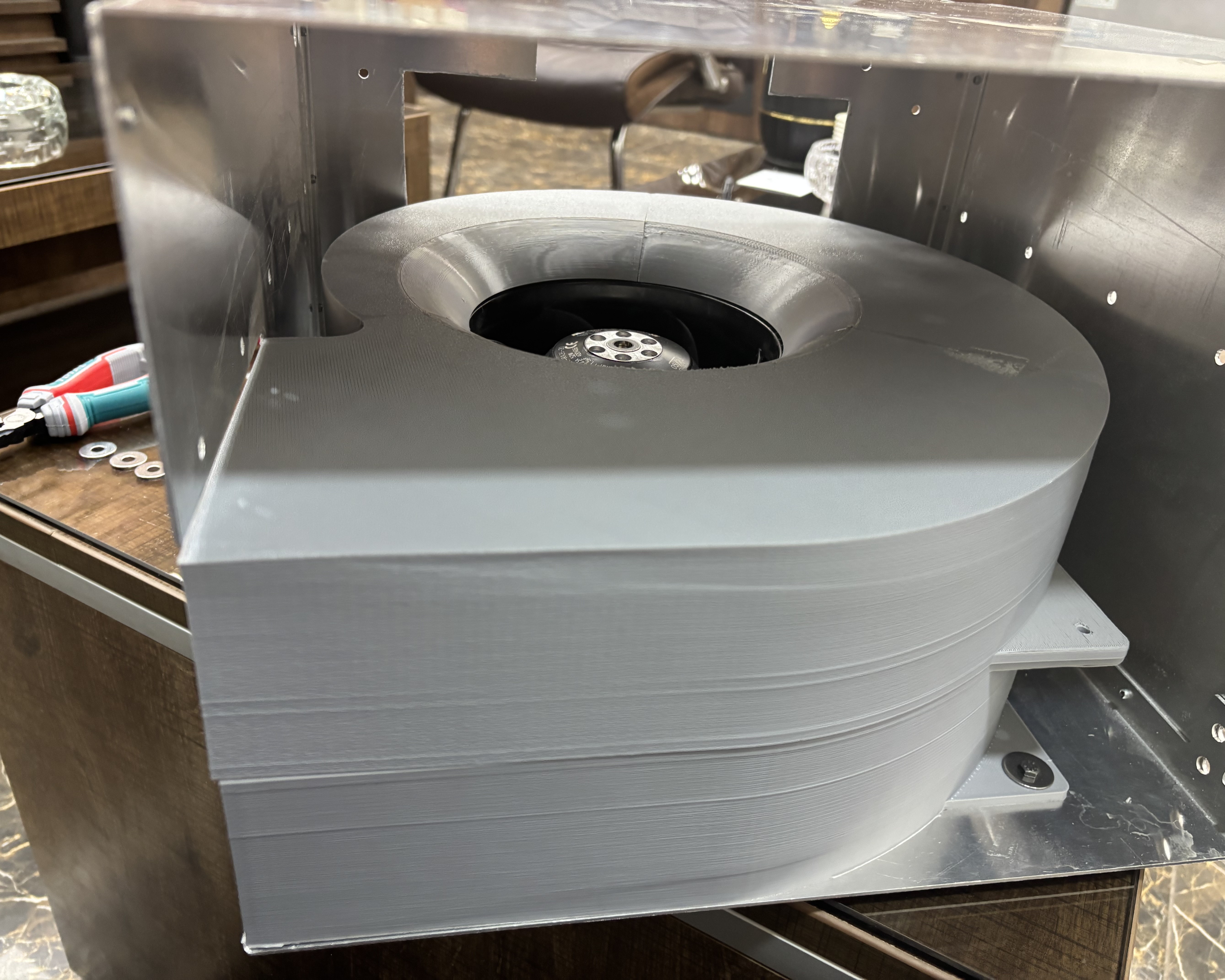
- A scroll housing for the fan. Designed and built to the fan's own specification, so the existing fan finally drives its air through a proper volute instead of losing it to open space.
- Faired the bends. Reshaped the duct turns that carried 91 percent of the pressure loss, cutting the resistance the fan had been fighting.
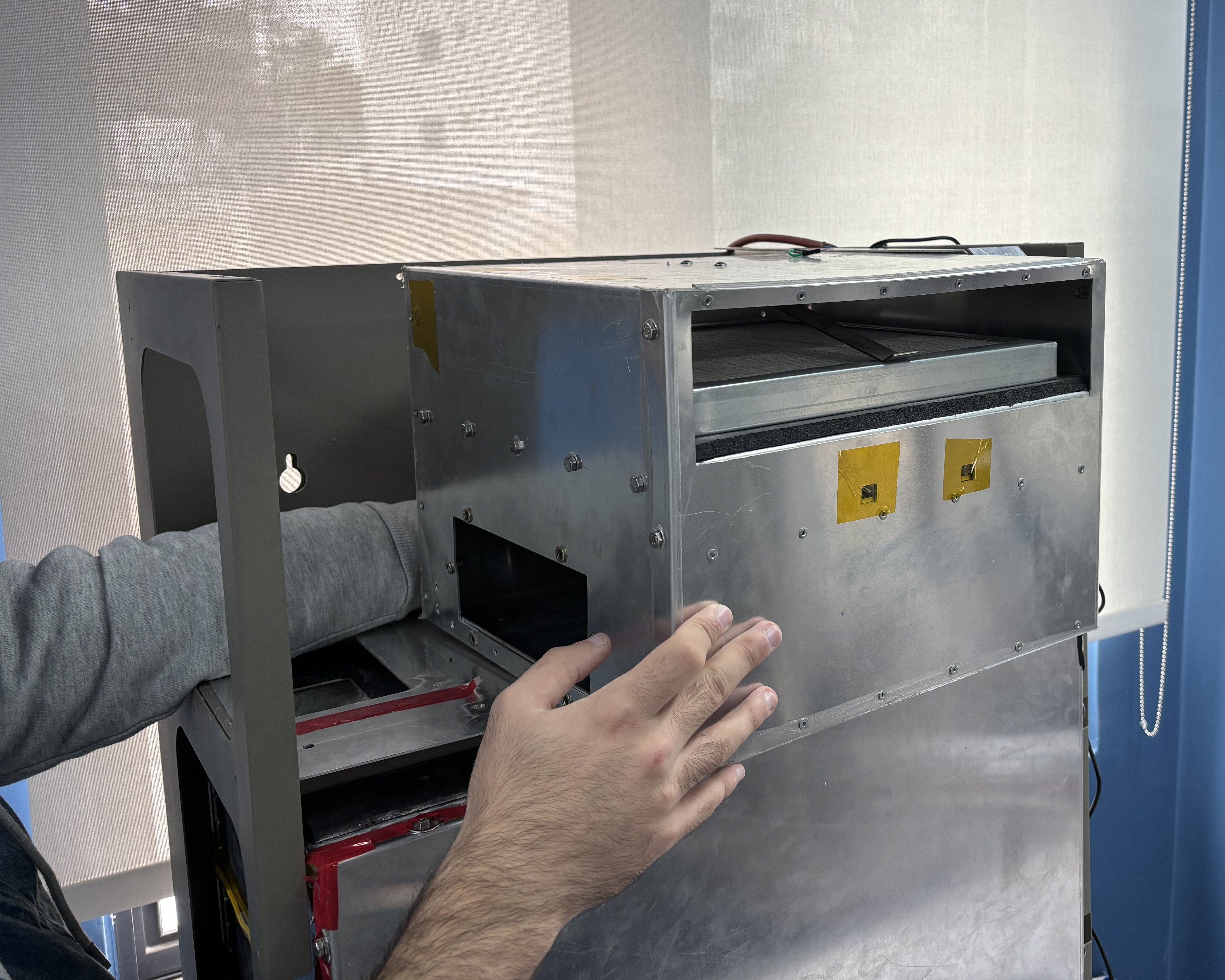
- Sealed the sorbent box. Replaced the leaky riveted sheet-metal tray with a sealed plastic enclosure, stopping air from bypassing the bed and stopping sorbent dust from escaping.
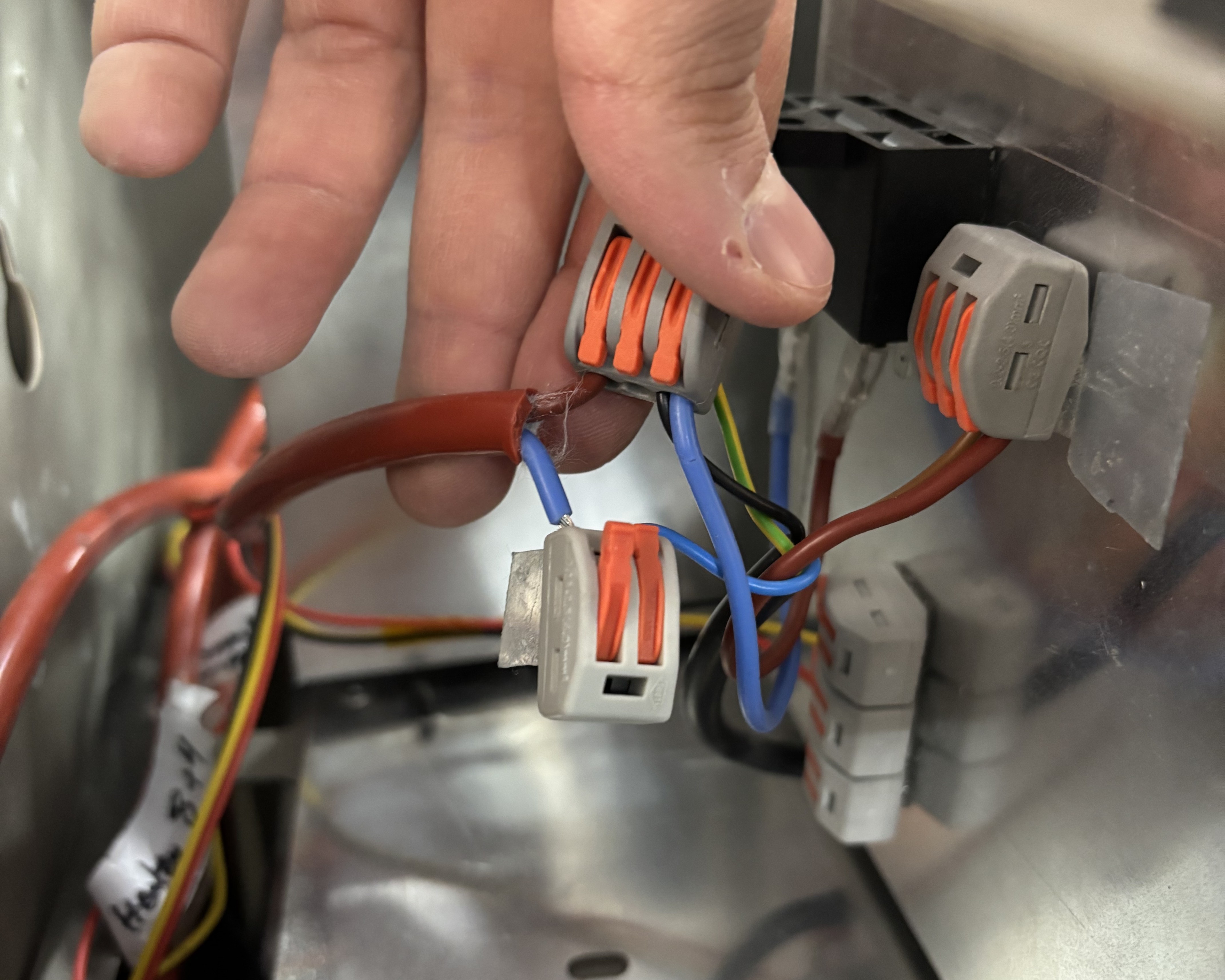
- Held the heat in. Insulated the bed and added insulating holders at the tray and insulation joints, so heat could not escape through the mounting bolts. Cut the desorption airflow to what the cycle actually needed, dropping the heater power that had been the biggest energy drain.
From model to hardware
The redesign was carried all the way to parts on the bench, under a tight clock.
- CAD and suppliers. Modelled the new parts in SolidWorks, worked from supplier dimensions, and built each piece to be made, not just drawn.
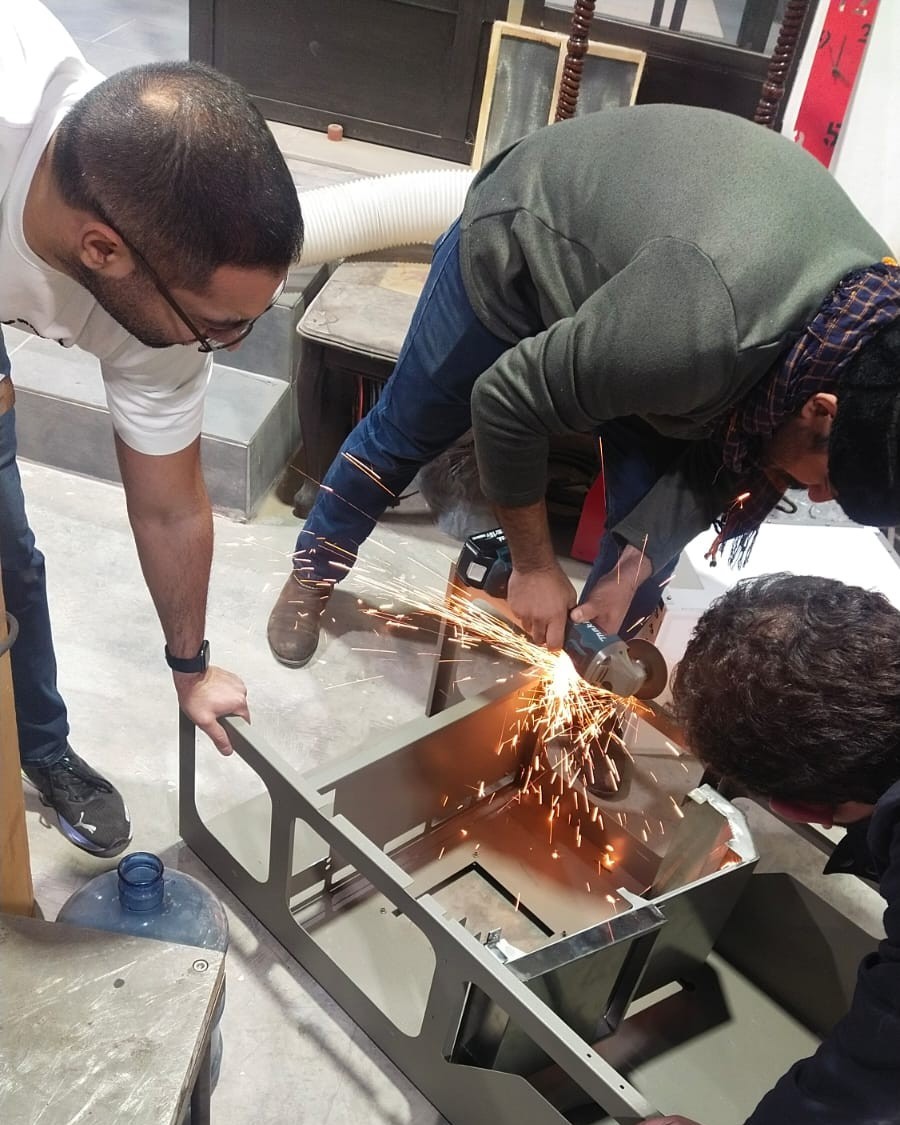
- Made and assembled. 3D printed the scroll housing and duct, finished and bonded them, fitted them into a sheet-metal case cut locally, and sealed the seams.
- Built the tray system. Set the spacing between the sorbent trays in the stack.
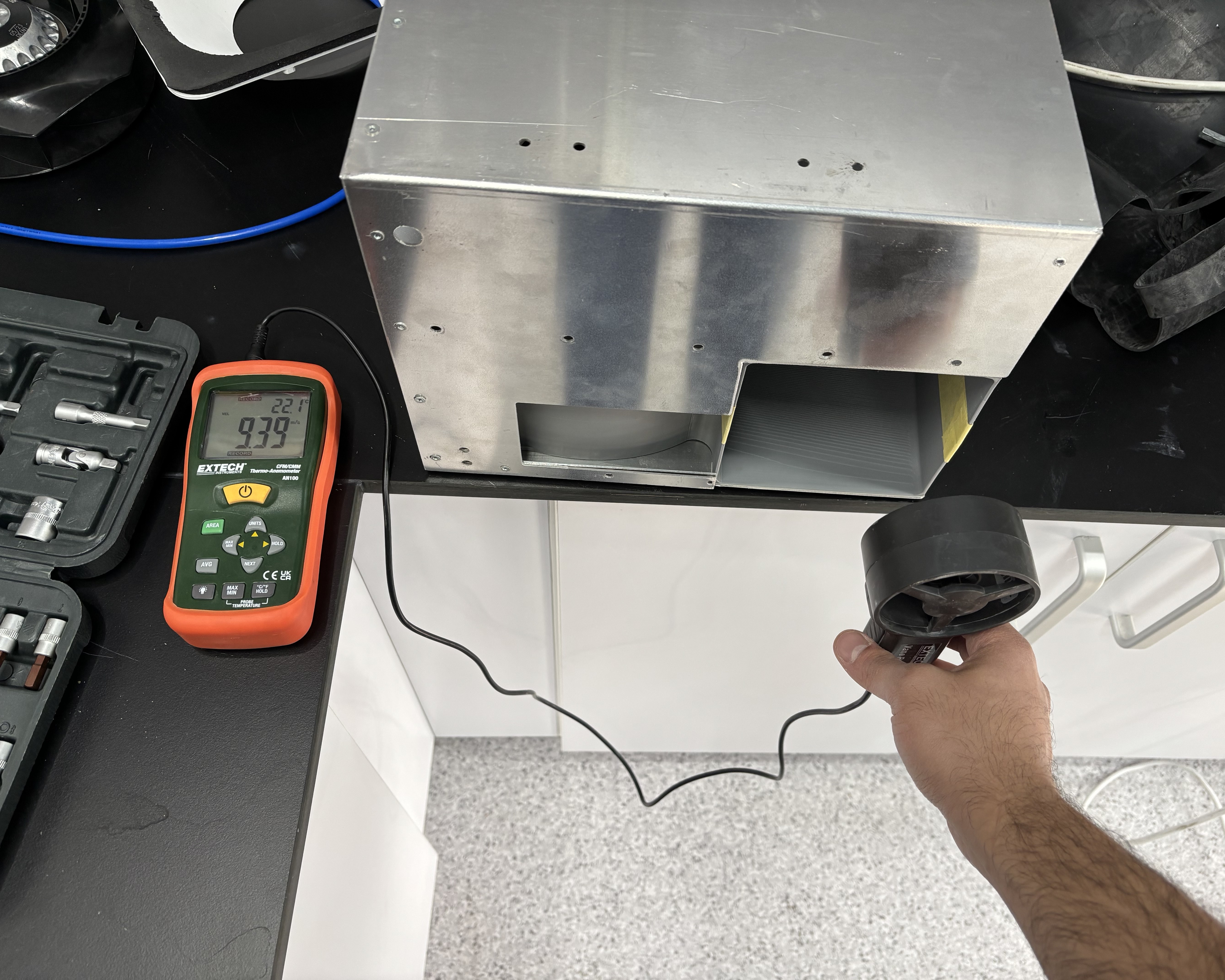
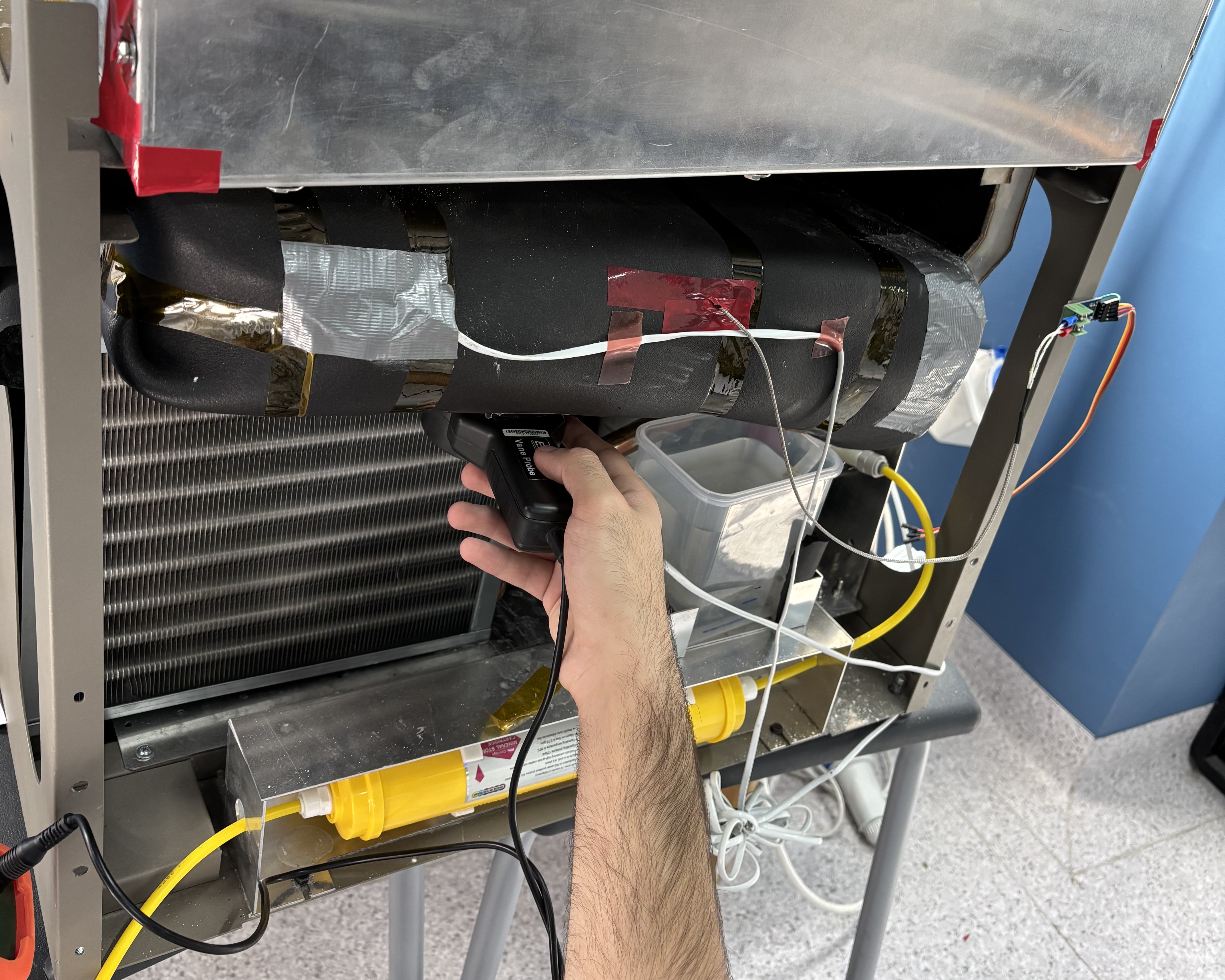
- Tested. Ran the rebuilt air path on the bench and measured the result against the model.